
Last-to-fill zones
Air collects where flow arrives last. Mark those ends on CAD and note the intended gate.
Venting
Venting is mold steel, but trap zones are designed in CAD. Mark last-to-fill ribs, bosses, and pockets before steel is cut. Do not jump first to higher speed or pressure.
Design guideline
Venting is the path that lets displaced air and process gases leave the cavity as plastic fills. Poor venting shows up as burn marks, short shots, splay, or weak weld lines.
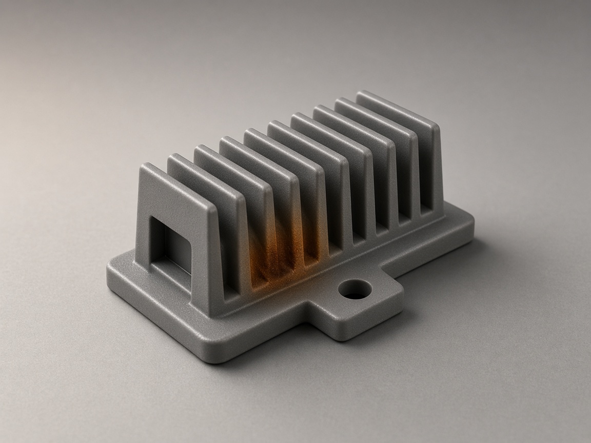
Part geometry often decides where vents must go: deep ribs , blind bosses , enclosed pockets, and last-to-fill zones. Mark those regions on CAD. Do not jump first to higher injection speed or pressure. DFM review flags trap zones before steel is cut.
The air-traps and burn-marks pages own those defects. Short shots cover incomplete fill. The vent glossary defines the steel feature. The design guide hub lists every topic.
Roles
Stay here for CAD trap zones. Open a sibling for the defect, the feature, or the CAD check.
| If you need | Open |
|---|---|
| Burn marks on a molded part | Defect causes and prevention |
| Short shots or incomplete fill | Fill that stopped before the cavity packed |
| Weld line strength | Two flow fronts and how they meet |
| Rib geometry rules | How to size the rib, not only how to vent it |
| Boss geometry rules | How to core the post, not only the pocket |
| How NetProto checks CAD | DFM review before steel is cut |
Checks
Qualitative checks. NetProto does not publish a vent-depth specification.
Last-to-fill zones
Air collects where flow arrives last. Mark those ends on CAD and note the intended gate.
Deep ribs
Melt can fill the wall first and trap air at the root. Flag deep or packed ribs for a local vent path.
Blind bosses
A closed pocket at the core tip has no path to the parting line. Core the boss and mark the pocket.
Weld-line convergence
Two fronts meet and squeeze air. Mark the knit and do not over-tighten a cosmetic callout there.
Geometry
Fix the geometry first. Vent steel is sized after the trap zone is known.
| Part feature | Why it traps air | Design action before tooling |
|---|---|---|
| Deep ribs | Melt fills from the wall and pushes air to the root | Keep the rib from becoming a deep thin pocket, add a fillet, ask for a root vent |
| Screw bosses and blind holes | Closed pocket at the core tip | Core the boss. Note a vent pin or insert vent if the pocket stays |
| Enclosed pockets | No path to the parting line | Open a path, move the feature, or specify a local vent |
| Weld-line zones | Two fronts meet and squeeze air | Place a vent near the convergence. Keep the cosmetic callout honest |
| Thin-to-thick transitions | Flow slows and air lingers | Use a gradual wall transition |
| Textured or deep surfaces | Fill resistance and release both get harder | Add draft and review the texture before steel |
Concepts
Methods only. This page does not publish vent land or depth numbers.
| Concept | What it means |
|---|---|
| Air trap | A pocket where gas cannot reach a vent before the melt seals it off. |
| Last-to-fill zone | The last place the flow front arrives. That is the first place to mark. |
| Parting-line vent | The default escape at the split. Features that never reach the split need a local path. |
| Ejector-pin, insert, or porous vent | Local steel methods when the trap sits away from the parting line. The toolmaker picks the method. |
| Diesel effect | Compressed air heats and can burn the resin at the last-to-fill spot. |
| Vent depth versus flash | Too shallow and gas stays. Too deep and melt can flash. No NetProto depth on this page. |
Diagnosis
Industry diagnosis logic. Not a process recipe and not a NetProto parameter set.
| What you see | What to check first |
|---|---|
| Burn at the same spot every shot | A vent is missing, clogged, or too shallow at a designed-in trap zone. |
| Burn moves shot to shot | Process instability. Still confirm CAD trap zones before chasing speed or pressure. |
| Draft angle | Deep or textured ribs need more draft so they release and can still be vented |
| Wall thickness | A thin-to-thick step can stall flow and leave air in the thick zone |
| Gate location | The gate sets the last-to-fill zone. That is where vents usually must sit |
Decision
Wrong: treat every burn as a process knob. Right: mark last-to-fill geometry first.
RFQ
The quote can start from CAD alone. These notes make the DFM pass specific.
Last-to-fill zones marked on CAD
Deep ribs and bosses flagged for vent access
Enclosed pockets reviewed for an escape path
Weld-line zones identified
Resin grade, texture, and wall notes in the RFQ
DFM review requested before steel is cut
Related
This page owns trap zones in CAD. Open a sibling for the feature, the defect, or the CAD check.
The defect when air has no path. This page is the CAD map that prevents it.
Air trapsCompressed-air burns at a last-to-fill spot. Check geometry before raising speed.
Burn marksHow NetProto checks trap zones on your CAD before steel is cut.
DFM reviewFAQ
Venting is the path that lets displaced air and process gases leave the cavity as plastic fills. Poor venting shows up as burn marks, short shots, splay, or weak weld lines. Part geometry often decides where those paths must sit.
The vent is cut in steel, but trap zones are designed in CAD. Deep ribs, blind bosses, enclosed pockets, and last-to-fill areas create places air cannot reach a parting-line vent. Mark those zones before steel is cut.
Melt can fill a rib from the wall first and push air to the root. A screw boss or blind hole is a closed pocket at the core tip. Core the boss, keep the rib from becoming a deep thin pocket, and ask for a local vent path.
Trapped air is compressed as the cavity fills. That heat can burn the resin and leave a dark mark at the last-to-fill spot. The burn-marks page owns that defect. This page owns the geometry that put the air there.
NetProto does not publish a vent-depth specification. Too shallow and gas stays in the cavity. Too deep and the melt can flash. Resin, texture, and feature location change the land. DFM review comments on the geometry; the toolmaker sizes the steel.
This spoke owns CAD trap zones and what to mark before tooling. Air-traps and burn-marks own those defects. DFM review is how NetProto checks your CAD. The vent glossary defines the steel feature.
Next step
Share geometry, resin, texture, and suspected last-to-fill zones so review can flag trap zones before steel is cut.