
Changes that rarely move cycle much
- Minor rib fillet tweaks within the same wall stack
- Secondary text on non cosmetic faces
- Label recess depth within existing wall
Glossary
Cycle time sets piece price. See the molding loop breakdown, why cooling dominates, and how cavitation and wall thickness affect output per hour.
Glossary
Every second in the mold is resin, energy, and machine rent rolled into unit cost.
Cycle time spans mold close, fill, pack, hold, cooling, screw recovery, mold open, and ejection. Cooling usually dominates once fill and pack are stabilized. On poorly gated or vent limited tools, fill imbalance can still waste seconds.

Cosmetic textures and thick bosses extend cooling because heat must leave the part before ejection.
Buyers asking for cycle time on day one of an RFQ should expect qualified estimates after tooling and resin are fixed.
Breakdown
Use this list when you compare quotes or read a cycle time breakdown chart.
Mold close
Fill
Pack and hold
Cooling (often roughly 60 to 80 percent of total cycle on many thermoplastic parts)
Screw recovery (can overlap with cooling on many presses)
Mold open
Ejection and part handling
Cooling dominates on most thermoplastic parts with moderate wall sections. Fill and pack are often seconds; cooling can be tens of seconds.
Cooling
Wall thickness and steel cooling layout matter more than minor cosmetic tweaks.
Cooling time scales approximately with the square of wall thickness. Doubling wall thickness can roughly quadruple cooling time.
Thick bosses and uneven wall sections drive cycle up more than rib height or label recess depth within the same wall stack.
Drivers
Which inputs move seconds per shot versus parts per hour. Confirm on your tooling RFQ.
| Driver | Effect on cycle | Controlled by |
|---|---|---|
| Wall thickness | Cooling time rises with thicker sections | Product design and DFM |
| Material (melt temp, HDT, flow) | Fill speed, cooling duration, safe ejection temperature | Materials specification |
| Cooling channel layout | Largest mold side lever for cycle reduction | Tooling engineering |
| Gate, runner, and hot runner type | Fill balance, pack time, scrap | Tool design |
| Cavitation | Output per cycle, not seconds per shot | Program and sourcing |
| Ejection and automation | Open, eject, and close segment length | Process engineering |
| Screw recovery rate | Can hide inside cooling or extend cycle if undersized | Press selection |
Drivers
Which design changes actually move the needle, and which do not.
Production
Qualified cycle on one production mold compounds on every repeat order.
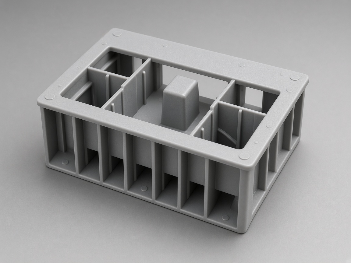
Cooling line layout on mold steel
Go deeper
Wall, resin, runners, cavitation, and volume programs connect to seconds per shot.
Parts per cycle from impression layout.
Cavity countMelt volume the screw delivers each cycle.
Shot sizeRunner type affects fill balance and scrap.
Hot runnerUniform walls shorten cooling.
Wall thickness (DFM)Lead time versus seconds per shot.
Cycle time tooling guideWhen cavitation and cycle dominate math.
High volume moldingPress size ties to projected area and pack.
TonnageVisual reference
Images are selected from the NetProto Forge media library for this topic.
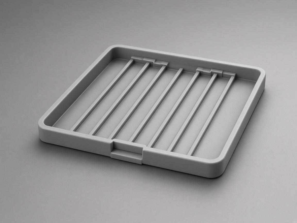
Thin wall parts on production tray
Thin wall parts on production tray
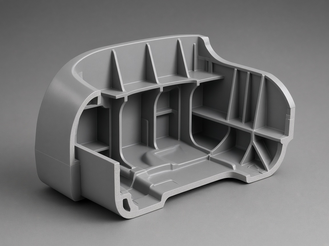
Wall thickness inspection on drawing
Wall thickness inspection on drawing
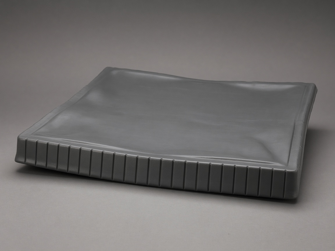
Multi cavity production output
Multi cavity production output
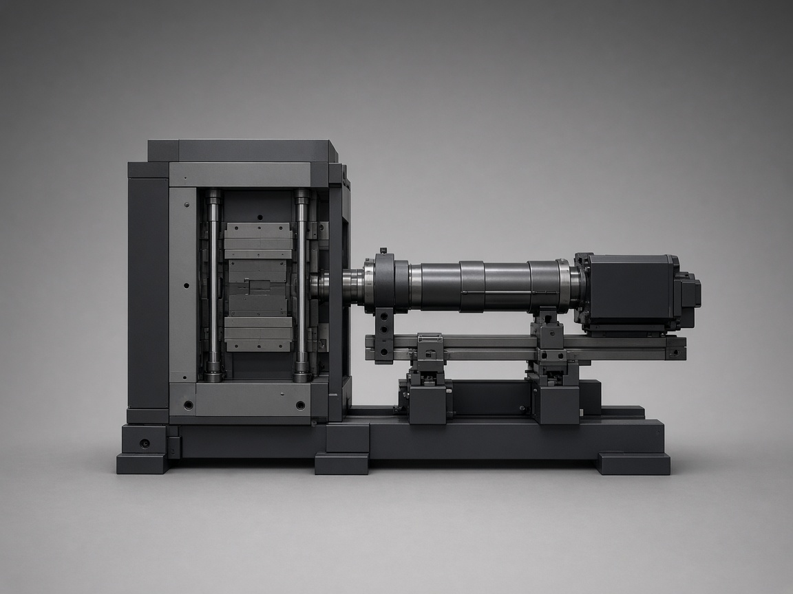
Finished housings from hardened tool
Finished housings from hardened tool
FAQ
It varies widely. Thin wall packaging can run sub ten second cycles on some lines; general thermoplastic housings often run longer; thick wall or high heat resin parts run much longer. Scope cycle after tooling and resin are fixed.
Not directly. Higher cavitation increases tool cost and cooling complexity but spreads machine time across more parts per cycle. Family mold versus multi cavity tradeoffs balance tool capital against cycle economy.
Yes, but state it as a production requirement, not a guarantee. Include resin grade, wall stack, cosmetic requirements, cavitation, and annual volume so the molder can engineer toward it.
Usually, but only if quality, scrap, and secondary operations stay stable.
Wall thickness drives cooling need, but gate, material, cooling steel, and ejection matter too.
Production cycle targets are discussed on qualified programs after tooling scope is defined.
Next step
Upload CAD for piece price tied to the hardened mold you will run repeat orders on.