
Single cavity first tool
- Lower upfront tooling before volume proves out
- Simpler fill balance tuning
- Common when geometry is large or cosmetic risk is high
Glossary
The mold cavity is the exterior forming half of the tool. Surface finish and layout drive cosmetics, cycle, and piece price.
Definition
The mold cavity is the stationary half of the mold, usually the A side, that forms the exterior of the part.
It is the impression into which molten plastic is injected. Cavity surface finish sets the ceiling for exterior cosmetics after texture, resin, and pack.
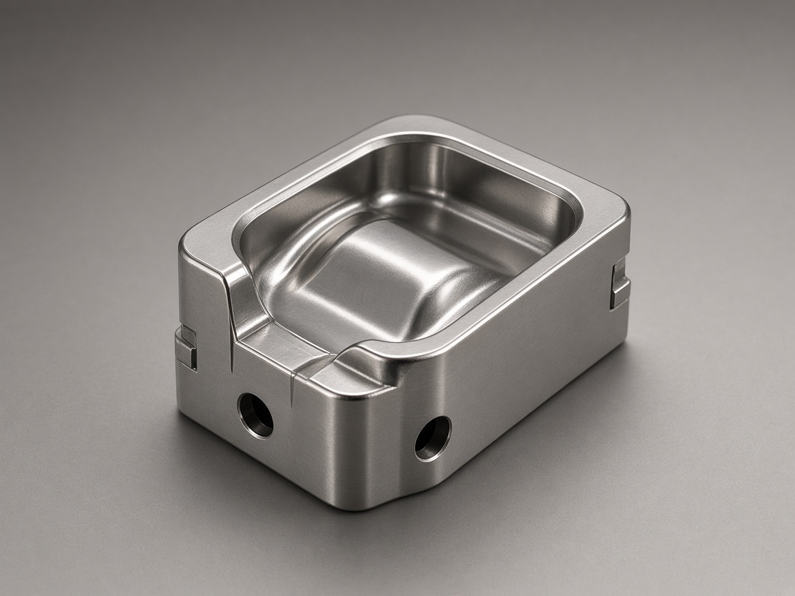
While the core forms internal geometry such as ribs, bosses, and inside walls, the cavity defines the external shape customers see and touch.
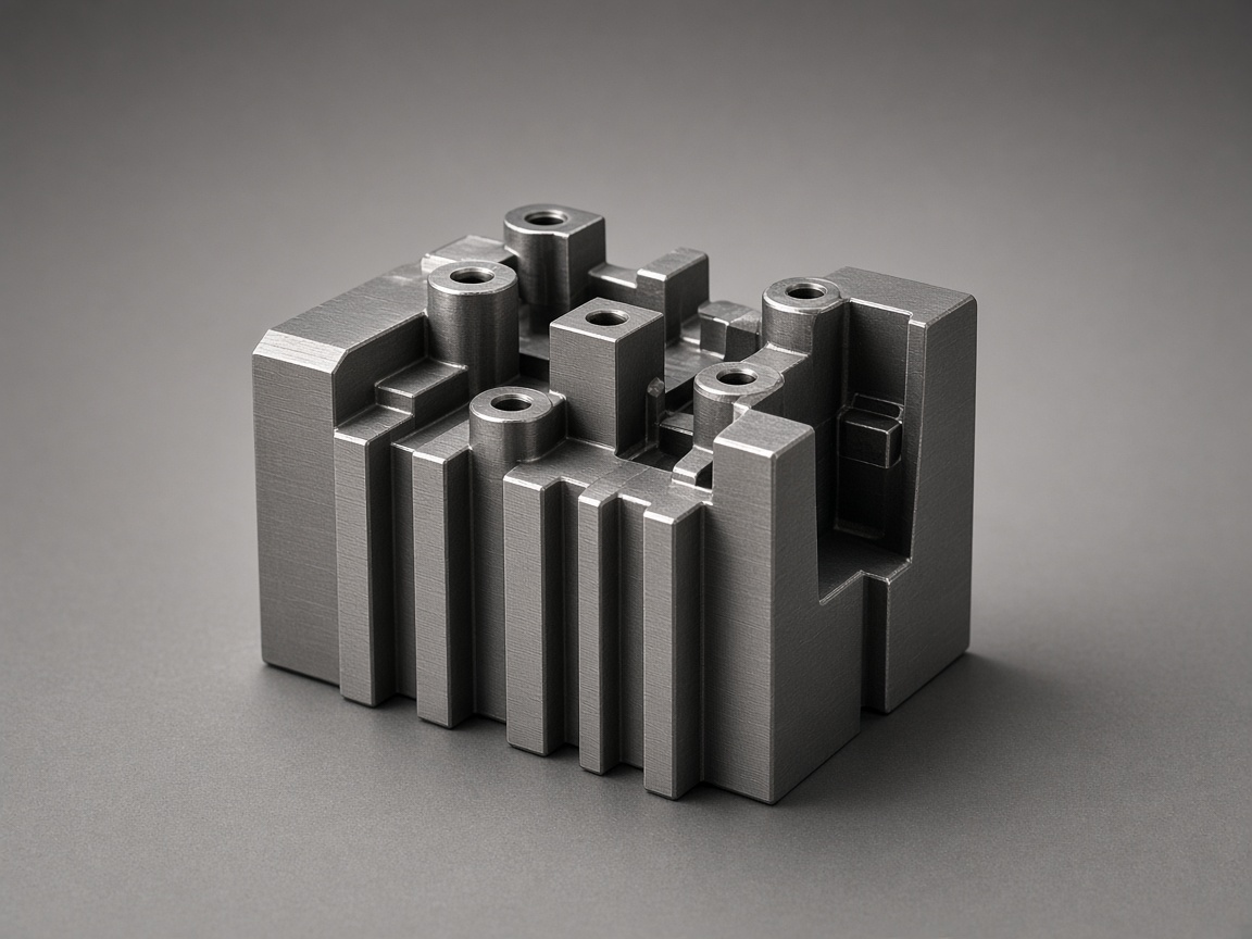
Multi cavity tools duplicate the same cavity to raise output per cycle. Family tools combine unlike parts in one mold base when volumes justify shared tooling.
Tooling
Cavity side examples: polished land, parting lines, and multi cavity impressions.

Design
Cavity side cooling removes most of the heat from the part. Uneven cooling can drive differential shrinkage, warpage, and longer cycles.
Class A surface identification on the CAD model
Texture spec or SPI finish target if already selected
Parting line location relative to visible edges
Draft direction tied to the cavity pull
Cooling layout notes when large cosmetic faces need uniform shrink
Layout
Cavity count is a capital versus piece price trade, not a free multiplier. Multi cavity tools also need balanced runner geometry, consistent cooling cavity to cavity, clamp force sized to total projected area, and vent paths for every impression.
Cavity side red flags
These issues often show up as flash, drag, burn, or cosmetic witness at T0.
Deep draw with insufficient draft leading to drag marks on cavity walls
Thin unsupported cavity steel that can deflect under injection pressure
Complex parting lines with flash risk at mismatch
Polished cavity land near the gate without a plan for gate blush or flow marks
No vent path at last fill areas risking burn or short shot on the cavity face
Go deeper
Each link is a different angle on the same program, not a duplicate definition.
Interior half and ejection context.
CoreWhich mold half mounts where.
A side and B sideAir must leave as plastic fills the cavity.
VentUnlike parts sharing one mold program.
Family moldingVisual reference
Images are selected from the NetProto Forge media library for this topic.

Polished mold cavity surface on exterior housing tool
Polished mold cavity surface on exterior housing tool
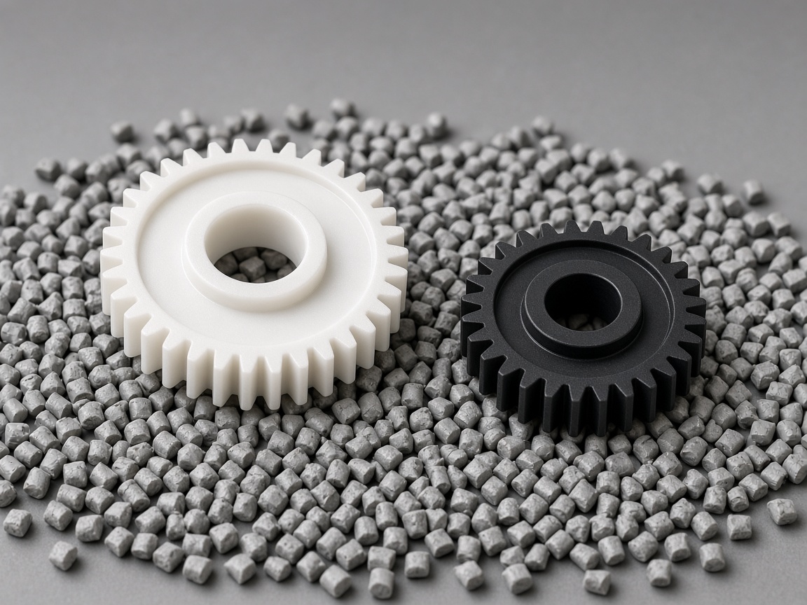
Parting line on injection mold cavity half
Parting line on injection mold cavity half
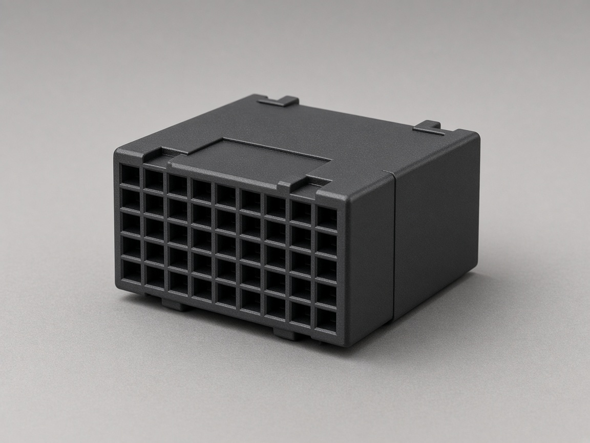
Multi cavity mold impressions in cavity plate
Multi cavity mold impressions in cavity plate
FAQ
The cavity forms exterior surfaces. The core forms interiors, ribs, and bosses. Many cosmetic faces and texture specs target cavity steel.
Single cavity molds one part per cycle. Multi cavity molds duplicate impressions to raise output. Multi cavity adds runner balance, cooling consistency, and venting work per impression.
The cavity side is the mold half that forms the outside of the part. Shops often call it the A side, but confirm on the tool design print.
Shops often call the cavity the A side, but always confirm on the tool design print.
Insert cavities are common when only one region of the tool changes between revisions.
Steel polish sets the ceiling. Texture, resin, and pack also shape what you see.
Runners must deliver equal flow to each impression. Imbalance shows as size or weight variation part to part until steel or process is corrected.
Choice depends on polish retention, wear at the gate, corrosion exposure, and repair strategy. Discuss pre hardened, hot work, or stainless mold tooling options with your mold maker rather than naming grades on the RFQ alone.
Next step
Upload CAD with Class A faces and parting line notes before steel cutting begins.