
Thermal shrinkage
The melt contracts as it cools. Thicker zones stay hot longer and can shrink more than a nearby thin skin.
Shrinkage compensation
The cavity is cut larger than the print so the cooled part lands on the callout. Datasheet shrink is a starting range, not a universal factor. DFM review comments on your CAD before steel is locked.
Design guideline
Shrinkage compensation means making the mold cavity larger than the target part dimension so the cooled part lands on the print callout.
Three mechanisms drive shrink: thermal contraction as the melt cools, crystallization in semi-crystalline resins such as nylon and POM, and orientation in filled materials. No single datasheet number covers every geometry. Wall thickness, gate distance, packing, and cooling all shift the real rate. NetProto does not publish a universal shrink factor. DFM review asks for material grade, critical dimensions, tolerance class, and whether mold-flow analysis is needed before steel dimensions are locked.
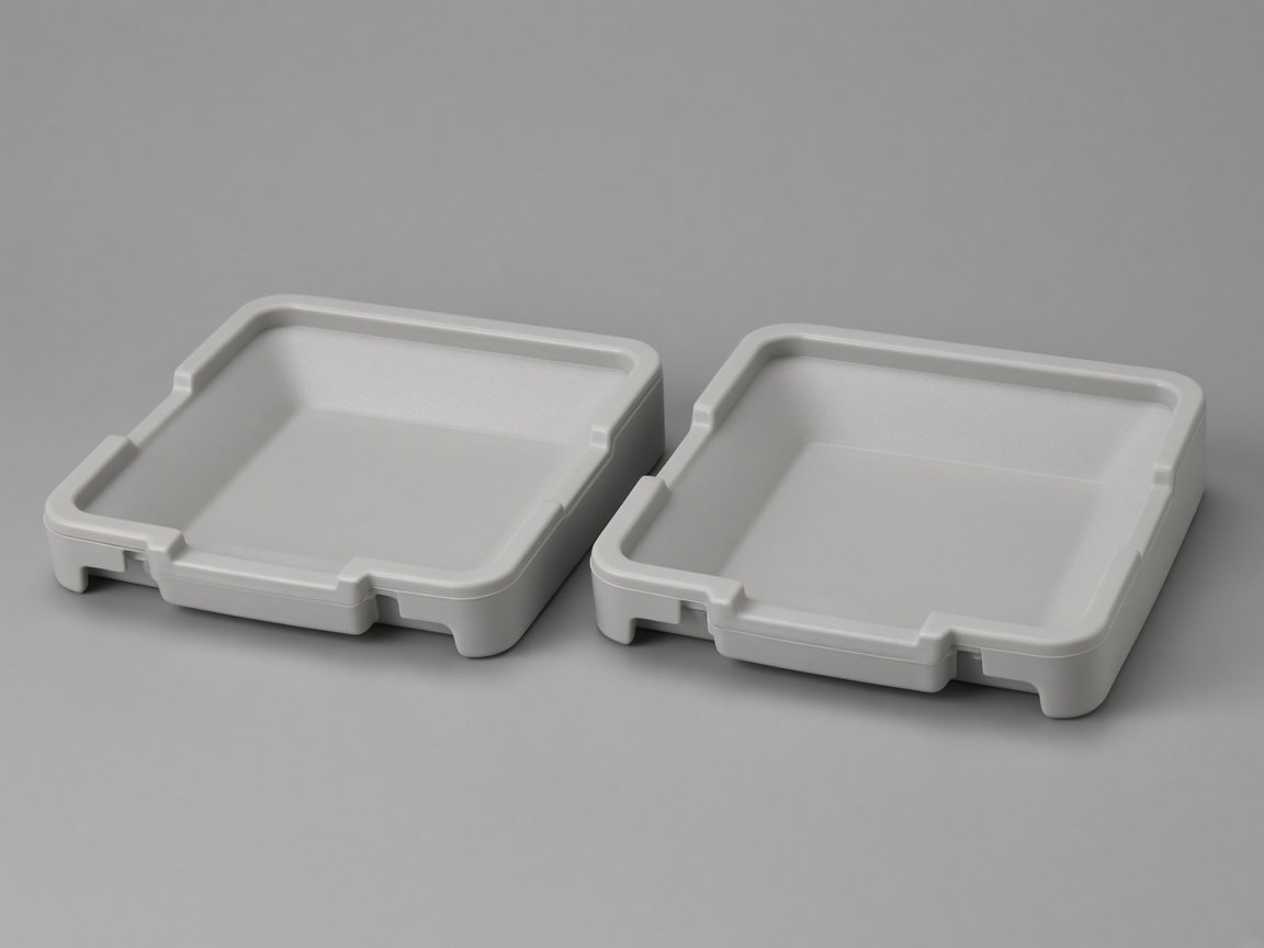
Send nominal part CAD. The mold is scaled. Commercial tolerance bands live on manufacturing standards and the standard tolerances spoke. Tight tolerances and GD&T own those methods. The shrink rate glossary defines the term. The design guide hub lists every topic.
Roles
Stay here for why parts shrink and how the cavity is scaled. Open a sibling for the tolerance method.
| Page | Use it for |
|---|---|
| Shrinkage compensation (this page) | Why parts shrink and how molds compensate |
| Standard tolerances | Default tolerance ranges for molded parts |
| Tight tolerance strategy | Tighter fits via material, process, and steel |
| Tolerance stack-up | Multi-part assembly accumulation |
| GD&T for molded parts | Datums and geometric controls |
| DFM review | Shrink assumptions checked before steel |
Checks
Qualitative references. NetProto does not publish a universal shrink factor or per-material table.
Thermal shrinkage
The melt contracts as it cools. Thicker zones stay hot longer and can shrink more than a nearby thin skin.
Crystallization shrinkage
Semi-crystalline resins keep shrinking as crystals form. Nylon and POM are common examples. Amorphous grades are usually more stable.
Orientation shrinkage
Filled materials often shrink less along flow than across it. That anisotropy is a warp driver on long, gated parts.
Steel-safe approach
Leave extra stock on steel that may still need to come off after first shots. Removing steel is simpler than welding it back.
Decision
Uniform shrink scales the cavity. Differential shrink warps the part and needs a plan, not a single factor.
Drivers
These are qualitative drivers. This page does not publish a shrink table.
| Driver | Why it matters |
|---|---|
| Wall thickness | A thick section cools later and can shrink more than a thin neighbor. |
| Gate location and packing | Distance from the gate and how the part packs change local shrink. |
| Material type and filler | Family, crystallization, and fiber or mineral fill change rate and direction. |
| Cooling uniformity | Uneven cooling and uneven walls drive differential shrink and warp. |
Steel-safe
Typical shop practice. Not a promised tryout count or a NetProto shrink factor.
| Step | What it is for |
|---|---|
| Leave stock on critical steel | First steel is not fully to the final size on features that may still move. |
| Measure first shots | T1 parts show where shrink landed versus the print. |
| Remove steel to the print | It is easier to cut remaining stock than to weld steel back and recut. |
| Confirm on a later shot | The second check is for those fits, not a new shrink table. |
| Tolerance stack-up | How shrink and tolerance accumulate across an assembly |
| Wall thickness | Nominal wall is a primary shrink driver |
| Uniform wall thickness | Uneven walls drive differential shrink and warp |
| Gate location | Gate distance and packing change local shrink |
RFQ
The quote can start from CAD alone. These notes make the DFM pass specific.
Material grade, not only the family
Critical dimensions and fits that must land on the print
Tolerance class, or a pointer to the drawing standard
Cosmetic versus functional faces
Whether mold-flow is requested before steel is locked
Steel-safe agreement on those critical fits
Related
This page owns how the cavity is scaled. Open a sibling for the tolerance method or the CAD check.
How NetProto checks shrink assumptions before steel is cut.
DFM reviewFAQ
Shrinkage compensation means the mold cavity is cut larger than the print so the cooled part lands on the callout. Send nominal part CAD. The mold is scaled. Do not pre-scale the model unless DFM review asks for it.
A datasheet shrink range usually comes from a plaque or a simple bar. Wall thickness, gate distance, packing, and cooling change the real rate on a part. Filled grades also shrink differently along and across flow. Treat the datasheet as a starting range, not a cavity scale.
Four drivers show up most often: wall thickness, gate location and packing, material family and filler, and cooling uniformity. Semi-crystalline resins such as nylon and POM add crystallization shrink. Glass or mineral fill adds orientation shrink.
Uniform shrink is a similar scale in every direction and is easier to offset in steel. Differential, or anisotropic, shrink varies by direction and thickness. That mismatch warps the part and is why mold-flow or a steel-safe plan may be needed on critical fits.
Steel-safe means leave extra stock on steel that may still need to come off after first shots. It is easier to remove steel than to weld it back and recut. That is typical shop practice, not a promised tryout count. T1 shots tell you where the remaining stock should come off.
Material grade, critical dimensions, tolerance class, and which faces are cosmetic versus functional. Note if you want mold-flow before steel is locked, and whether a steel-safe plan is acceptable on those fits. DFM review uses those notes before the cavity is cut.
Next step
Share geometry, material grade, critical fits, and tolerance class so review can check shrink assumptions before the cavity is cut.