Ejector Pin Marks on Cosmetic Parts: RFQ Keep-Outs
Ejector pin marks are small circular, oval, or ring-shaped witnesses left on a molded part where the mold's ejection system pushes the plastic off the core or cavity steel. They are normal on hidden or functional surfaces, but they become a program issue when they land on a declared A-side or Class-A cosmetic face. This guide focuses on how to specify ejection zones, surface finish, and inspection language before hardened steel is cut—not on troubleshooting an unexpected mark after T1. If you are comparing an interim tool elsewhere, see soft tooling vs hardened steel for cosmetic programs as a comparison, not as a NetProto tool menu.
What Are Ejector Pin Marks?
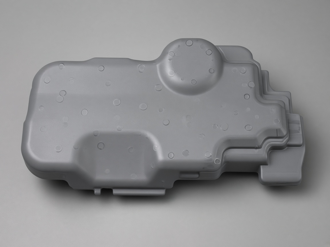
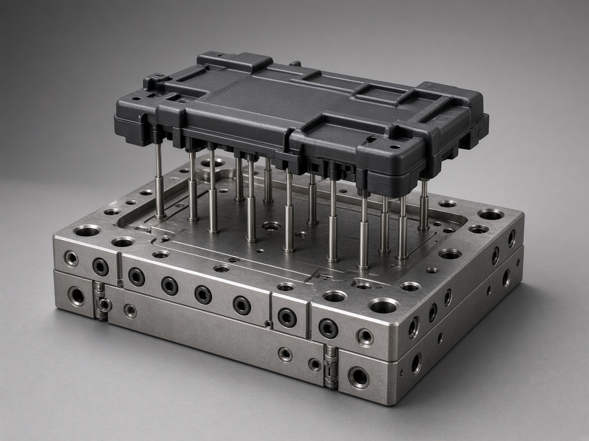
After pack and hold, the part shrinks onto core details and can grip cavity texture or undercuts. Ejector pins apply localized force at planned push points so the part releases without bending ribs or tearing thin walls. Where a pin face contacts the part, you often see a witness: a faint gloss change on polished steel, a shallow depression or raised pad, a ring at the pin perimeter, or stress whitening on tough resins.
Those traces are expected wherever ejection is allowed. The engineering question is not whether marks exist, but which faces may show them and how severe a witness is acceptable under your finish and lighting. Put both answers in your drawing notes to avoid subjective judgment calls during QC. For root causes, severity drivers, and corrective actions after you see a bad mark, see ejector pin marks in injection molding. The sections below translate cosmetic intent into RFQ and drawing language so tool design can route pins to B-side or textured zones early.
Key Facts
- Every ejected part has some trace of the ejection system; the real question is which face is allowed to show it.
- Cosmetic face (A-side) vs B-side ejection zones should be declared as keep-out zones on the RFQ, not discovered at T1.
- Texture can mask a witness; high-gloss, transparent, or Class-A faces tend to reveal pin contact more easily.
- Pin placement, draft, wall support, and surface finish are design decisions—see ejector pin placement for layout patterns that hide witness on the show face.
- Process tweaks may reduce severity, but they rarely erase a pin witness on a polished or appearance-critical face once the pin lands there.
- Do not treat generic pin diameters or mark-depth limits as supplier defaults; put acceptable witness appearance on your drawing or inspection plan, and tie dimensional bands to your commercial tolerance standard where needed.
- Ejection planning belongs in the same conversation as part surface finish options for SPI, VDI, and MoldTech texture codes, so push points and cosmetics are one system, not two late-stage edits.
Where Marks Are Usually Acceptable
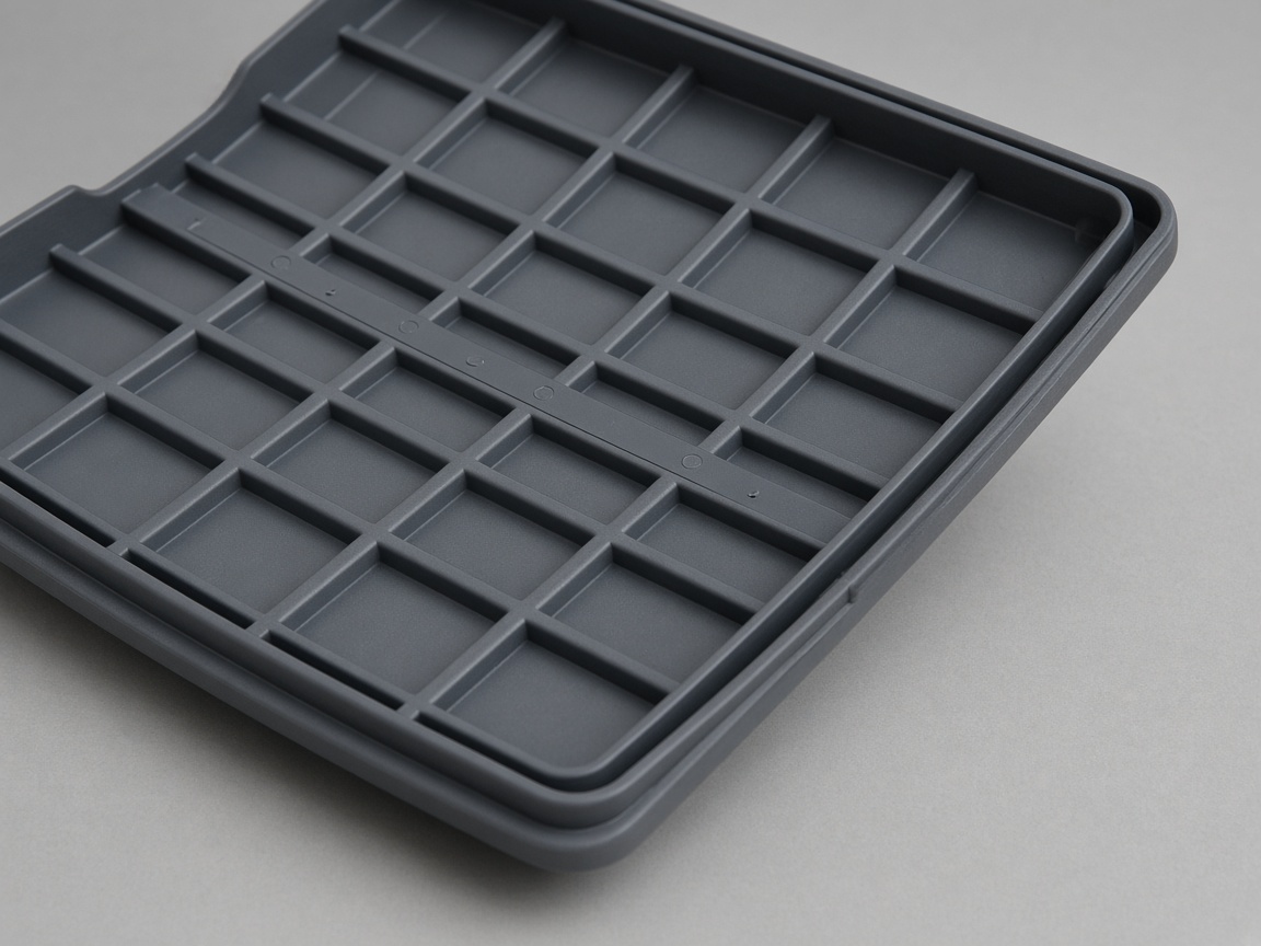
B-side surfaces, internal walls, pockets, ribs viewed only during service, recesses under labels or adhesive zones, and functional areas hidden after assembly are the natural homes for ejector pins. On many housings, the belt that sits against a chassis, the inside of a clip tower, or the floor of a battery bay can carry witness without affecting the buyer's first impression.
Texture specified for grip or scratch resistance also changes how a witness reads. A fine matte or medium VDI-style grain often scatters light so a pin ring becomes a subtle shading change instead of a glossy coin. When the part's installed orientation means the mark is never seen or touched, document that face as an approved ejection zone on the RFQ so DFM does not need to guess.
Teams sometimes add a localized texture patch only where pins must land on an otherwise polished B-side. That is a valid trade if the patch boundary is called out and acceptable in T1 photos under your viewing distance and lighting.
Where Marks Must Be Planned Around
Exterior housings, lens windows, logo fields, soft-touch grips, sealing lands, and assembled mating surfaces that must stay flat or glossy are high-risk zones. Transparent or translucent materials telegraph gloss differences through the wall, so a pin on an inner surface can still read from the outside. Consumer electronics bezels and automotive trim panels with high gloss show even a faint ring as a cosmetic reject.
Plan ejection before steel is detailed: use keep-out faces on CAD, balance pin count with wall stiffness, and ask for a pin-layout sketch during tool design review. If the show face cannot tolerate any witness, the program needs alternate release—additional draft, stripper plate or sleeve ejection on hidden geometry, or redesign of rib/support so pins sit on designated pads. Those choices are less expensive on the screen than as weld or polish rework on a hardened tool. Sink on a thick show face is a packing problem, not an ejection-layout problem. See gas assist injection molding for sink-free thick sections when the issue is local mass rather than pin witness.
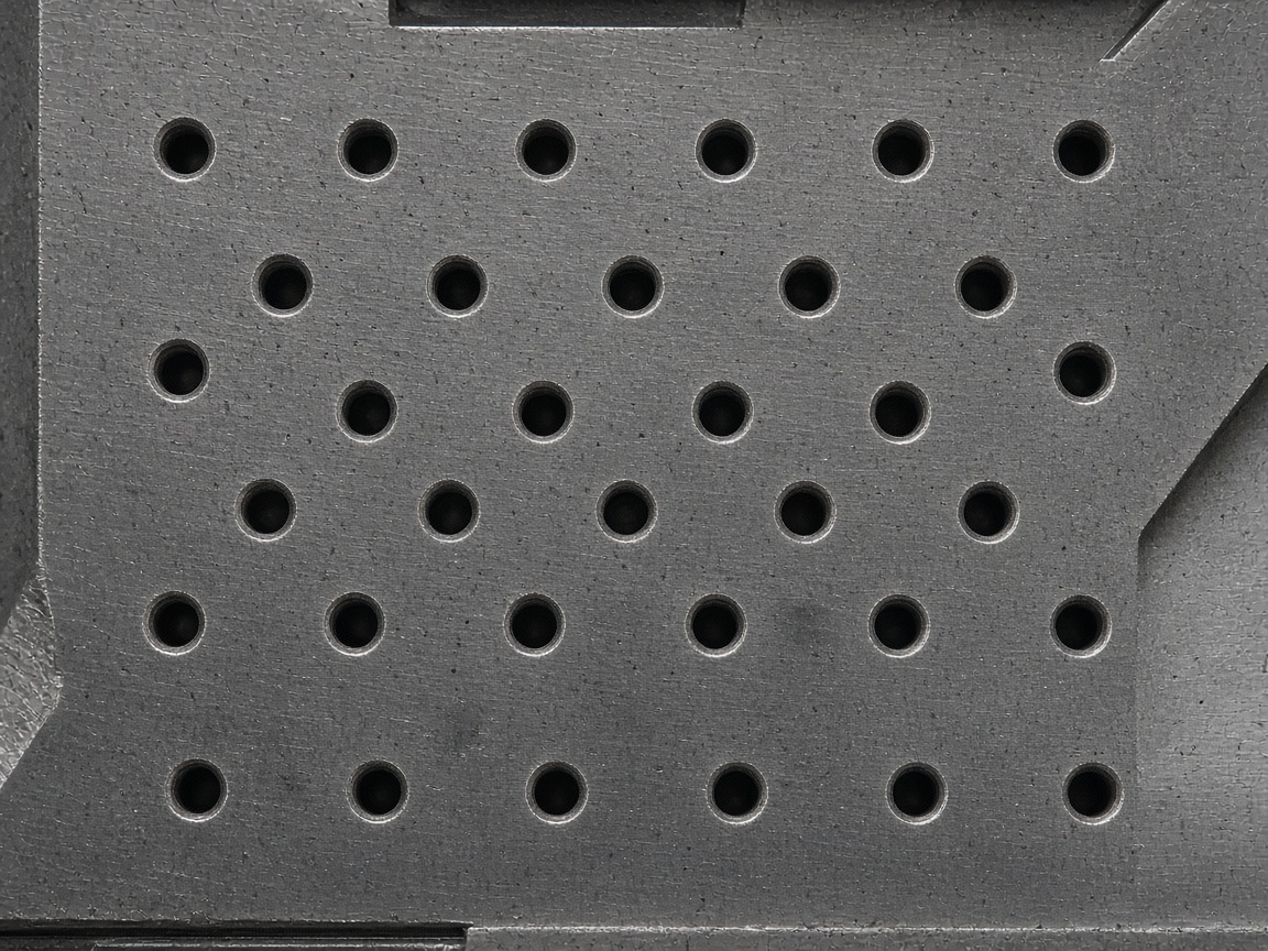
Pin locations in the mold are permanent features in the plate. Wire EDM and machining define hole position and clearance; moving a pin after T1 is a change order. That is why cosmetic keep-outs belong in the RFQ packet with the same weight as material and cavity count discussions.
Drawing and RFQ Language
Copy these five steps into your drawing notes for consistent cosmetic ejection specification. Use numbered notes so both your internal quality team and the molder share one definition of "cosmetic."
- Mark A-side / cosmetic faces that cannot show an ejector witness. Name them on a shaded view or a dedicated "cosmetic map" layer (for example: exterior A, lens ring, grip show surface).
- State the finish on those faces—SPI surface finish grades for cosmetic vs ejection faces, VDI or MoldTech texture code, matte texture, optical clarity for lens areas, or "no ejector contact permitted" where polish is specified.
- Name B-side or hidden zones where pins are acceptable, including optional texture patches if pins must sit near a transition.
- Request T1 photos of both sides before approving cosmetics, and ask for a pin-layout sketch from the tool design review with pin numbers mapped to cavity impressions.
- Upload CAD with cosmetic keep-out faces noted in the RFQ text and, when possible, in model annotations or a simple table in the drawing block.
Example RFQ sentence you can paste: "Exterior faces shown in view A-A are Class-A cosmetic: no ejector pin witness permitted. Ejection allowed on interior belt, rib tops, and pad areas shown in view B-B. Mold finish SPI A-2 on exterior; SPI D-3 on interior ejection pads. T1 submission to include lit photos of all cosmetic faces plus pin map."
When you use NetProto's platform, repeat the same keep-out summary in the project notes so DFM review can flag impossible pin routing before tooling release.
What T1 Photos Should Show
T1 cosmetic approval should be evidence, not a hallway conversation. Require these four items in your T1 submission package:
- Pin location mapped to cavity and pin number, not only a photo labeled "looks okay."
- Witness type: faint ring, gloss spot, shallow depression, raised pad, or stress-whitened area.
- Finish context: whether specified texture hides the mark at normal viewing distance and lighting (include one photo under representative light if gloss is critical).
- Both sides of the part when any show face wraps or when transparency can reveal inner witness.
Rule of thumb: If the mark is on a declared cosmetic face, treat it as a tooling or layout issue to resolve before production sign-off. If it is on an agreed hidden face, document it as the approved witness in your inspection record and move on. That split keeps teams from debating the same ring on every shipment. Update your inspection plan to reference the approved witness photos from T1 for ongoing production.