Gas Assist Injection Molding: When to Specify
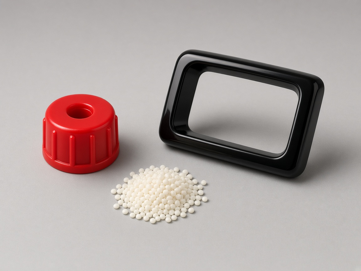
Gas assist injection molding uses a controlled gas channel to hollow out a locally thick section after the plastic fills the cavity. The remaining wall can pack from the inside, which often reduces sink on an opposite cosmetic face, limits warpage in heavy ribs, and cuts part weight without changing the exterior shape you modeled. This guide helps mechanical engineers decide when to write gas assist on an RFQ, not how to tune gas pressure at the press. Process tuning parameters stay with the molder; your RFQ should focus on geometry and cosmetic requirements.
What Is Gas Assist Injection Molding?
In a standard fill, molten plastic enters the cavity and solidifies from the mold wall inward. Thick bosses, grip bodies, and frame sections hold heat longer than surrounding thin walls. As the core shrinks, the surface can pull inward and show sink, or the part can bow when internal stress balances unevenly. Gas assist adds a second phase: after partial or full plastic fill, nitrogen (or another inert gas) enters through a controlled path and displaces plastic in the thickest region, leaving a hollow channel or pocket while the visible skin stays on the tool surface.
The buyer-visible geometry stays the same as your CAD outer surfaces. What changes is internal mass distribution and the way packing force reaches the cosmetic wall. Tooling must include gas pins, vents, and sequencing logic, so the decision belongs in the RFQ before steel is cut. For how the process fits NetProto molding capabilities and typical thick-section applications, see gas assist injection molding. That process page supports the specify-or-skip decision; it is not a press-setup recipe.
NetProto delivers plastic injection molding with DFM feedback before tooling release, instant CAD quoting, and one hardened steel tool built for the life of the part on qualified programs. If you are comparing an interim tool elsewhere, see soft tooling vs hardened steel for gas assist programs as a comparison, not as a NetProto tool menu. Gas assist, when required, is scoped on the drawing and validated during DFM and mold design, not added as an undocumented shop trial after the cavity is finished.
Key Facts
Review these key facts before writing gas assist on your drawing:
- Gas assist targets locally thick, heavy sections. It is not a default option for every housing, lid, or enclosure with uniform wall thickness.
- The usual buyer trigger is cosmetic sink or excess weight. Visible sink on an appearance face, or a handle or frame that feels heavier than the structural job requires, is the symptom that starts the conversation.
- Core-out and wall thinning in CAD come first. Coring out thick sections and adjusting wall thickness should be the first DFM moves before you lock gas assist on the RFQ.
- Gas channels change the mold design. The intent must be named before steel is cut. Retrofitting gas assist into a finished cavity is often expensive or impractical.
- Gas assist does not replace thin-wall design on large, flat panels. Long, thin flow paths and warp-prone panels still follow thin wall design rules; gas assist does not shorten fill length across a wide expanse.
- Process parameters stay with the molder. No gas-pressure values, hold-time recipes, or nozzle specifications belong on a buyer-facing spec sheet. Those settings are determined by the molder for your resin, geometry, and machine.
When to Write Gas Assist on the RFQ
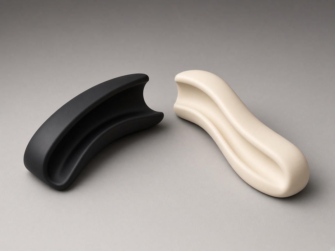
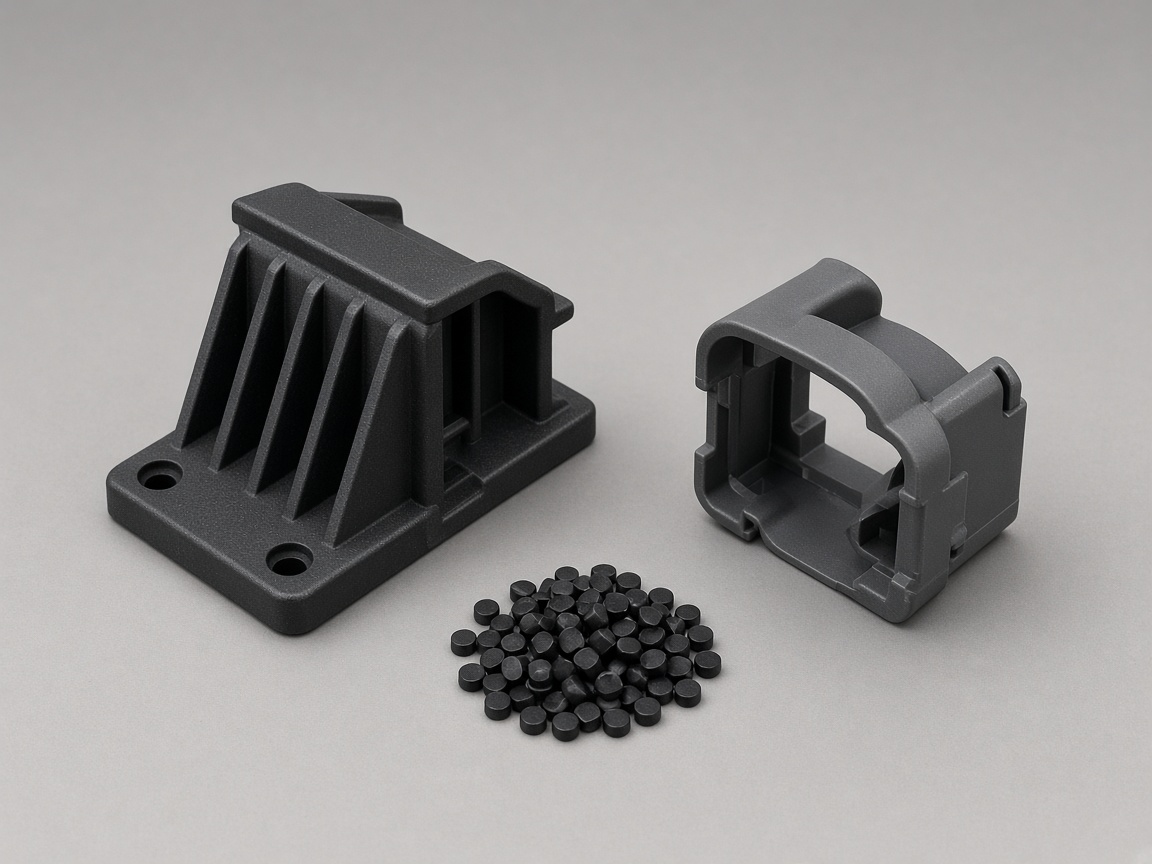
Specify gas assist when you have thick, functional mass that still sinks or warps after ordinary coring in the solid model. Common examples include power-tool handles, appliance grips, structural frames with deep ribs, chair arms, and large bosses on the hidden side of a cosmetic panel. The section is locally thick, the appearance face sits opposite the mass concentration, and you already tried removing material with cores, ribs, or wall reductions.
Discuss sink marks in injection molding with your molder before you treat gas assist as the only fix. Sink can also come from gate location, insufficient pack on a thin rib, or a boss tied to a thick wall without relief. Gas assist helps when the root cause is packing a thick section that you cannot thin further without losing stiffness or ergonomics.
Use this gas assist decision checklist before you write "gas assist required" on the drawing:
| Check | Pass when |
|---|---|
| Local thickness | One region is clearly thicker than the surrounding wall, not the whole part uniformly heavy |
| Cosmetic priority | The face that must stay sink-free is opposite or isolated from the gas channel path |
| Coring attempted | You removed internal mass in CAD or documented why a core-out would fail stiffness or assembly |
| Tooling timing | Gas assist is on the RFQ before mold design freeze, not as a post-cut engineering change |
| Alternative review | You asked whether a design change can eliminate gas assist without missing structural targets |
When to Leave It Off
Leave gas assist off the RFQ when the part already meets packing and cosmetic requirements with conventional tooling. Uniformly thin walls, well-cored housings, and sections that pack with normal hold pressure do not need a gas circuit. If ordinary shutoffs or a side action can core the mass without weakening the part, gas assist adds mold complexity without benefit.
Also skip the callout when you have not yet run DFM on the uploaded solid model. Ask for a DFM pass first. Reviewers may propose rib height changes, boss links to thinner walls, or gate moves that resolve sink without gas. Locking "gas assist required" too early can push the tool down a path that a simpler design change would have avoided. Request DFM feedback before freezing the tool concept to keep all options open.
Large, flat panels that fail fill or warp across the span are usually a thin-wall and flow-length problem, not a gas-assist problem. Route those programs through thin-wall design and gate planning before you add gas assist as a catch-all note. Small parts with local mass are a different problem than hollowing a grip. See micro injection molding for small thick-section parts when the issue is micro features rather than a gas channel.
How to Specify It Without Writing a Process Recipe
You do not need to write gas pressures or cycle times to get a useful quote. You need to communicate where the process matters and which surfaces must stay clean.
- Mark thick sections on the CAD file or drawing view. Use a shaded view, a section cut, or explicit notes on the 3D model so the molder sees the same volume you mean. Avoid a vague note on page one with no geometry reference.
- State the cosmetic face(s) that cannot show sink or witness marks. Separate cosmetic face (A-side) vs non-visible surfaces, call out SPI surface finish grades for cosmetic faces if texture is contract-critical, and note whether gas pin vestige must land on a non-visible edge.
- Write "gas assist to be considered" if you are unsure, or "gas assist required" if a prior molder validated the process on this geometry. The softer phrase invites DFM alternatives; the stronger phrase signals that you already rejected simpler coring on a similar build. Choose your wording based on how much design exploration you want from the molder.
- Ask the molder whether a design change can remove the need for gas assist altogether. Request a side-by-side opinion: cored CAD versus gas-assist tooling cost, risk, and cycle impact. NetProto's DFM review is built to surface those tradeoffs before tooling release.
- Upload CAD for DFM before you lock the tool concept or order steel. Use the instant quote platform so manufacturability feedback and pricing reflect the same geometry your molder will cut.
Related Process Guides
Use these pages when the design question is broader than the gas-assist RFQ callout:
- Gas assist injection molding for process scope and thick-section applications.
- Coring out thick sections when mass can still be removed in CAD.
- Thin wall design for long, thin flow paths that gas assist will not shorten.
- Sink marks in injection molding for packing and geometry levers that are not gas-specific.
NetProto does not publish gas-assist pressure tables or wall-thickness limits as company specifications. Use your drawing tolerances and SPI finish callouts for inspection; gas channel sizing is reviewed during mold design.