
Gate on visible cosmetic surface
- Witness mark and vestige need texture or offset design
- Pack marks may telegraph near the gate
- Trim or post gate removal adds handling
Glossary
A gate is the narrowed entry from the runner into the cavity. It controls fill, pack, vestige, and weld line placement.
Definition
A gate is the narrowest point in the feed system between the runner and the cavity.
The gate is an intentionally restricted opening. It generates shear heat, controls melt velocity into the cavity, and freezes first to seal the cavity during pack and hold.
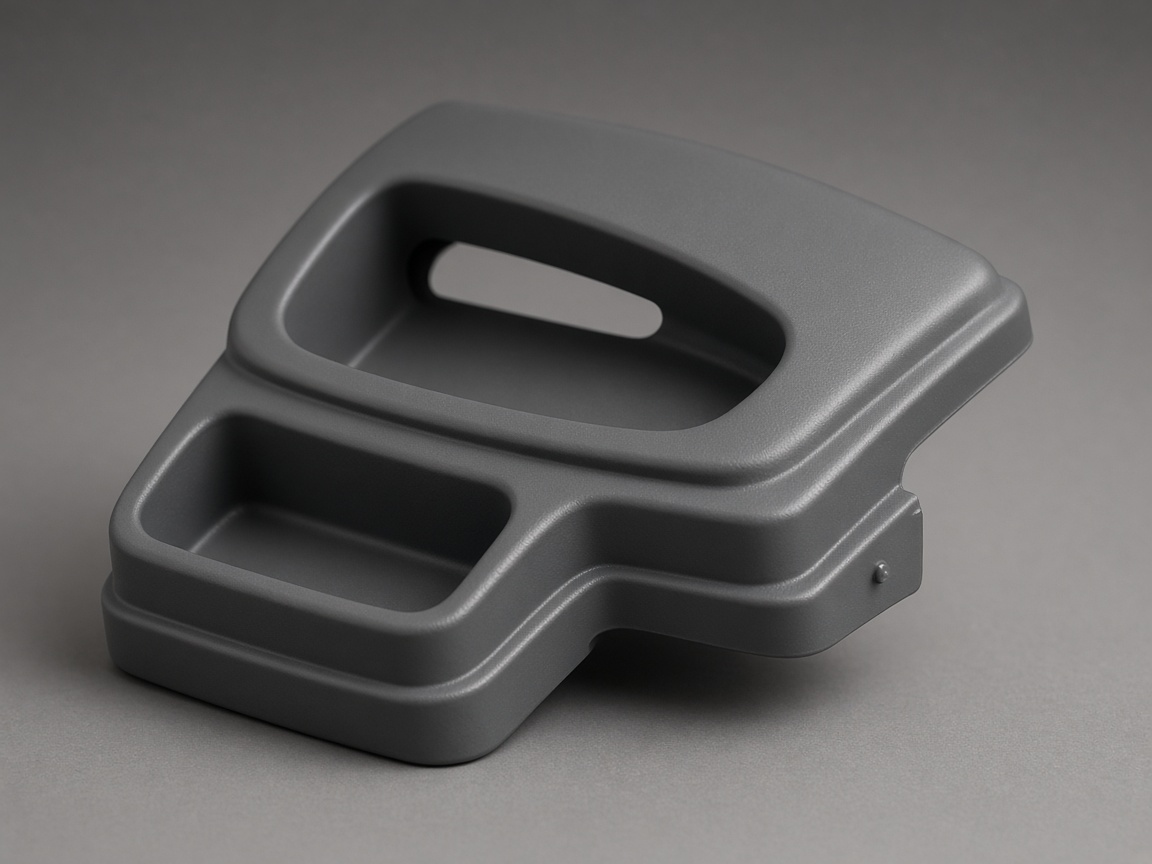
Gate style, size, and location affect weld line position, vestige, cycle time, and local strength.
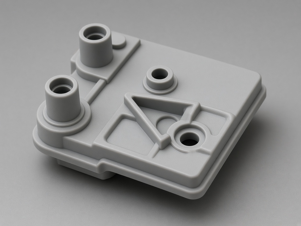
The runner feeds the gate. Gate location should be chosen with cosmetic faces in mind, not added after steel is cut.
Reference
Overview only. Vestige and trim depend on steel detail, resin, and process. See linked glossary entries for hot runner and valve gate depth.
| Gate type | Typical vestige | Trim or post work | Often used for |
|---|---|---|---|
| Edge gate | Medium tab or witness | Manual or automated trim | Flat parts, simple cold runner tools |
| Fan gate | Low, spread entry | Minimal trim on some layouts | Thin walls, wide fill fronts |
| Tab gate | Medium tab | Trim required | Thick sections, stress sensitive areas |
| Submarine (tunnel) gate | Low, hidden on parting | Often self trimming | Automated production, hidden edges |
| Pin point gate | Very small dot | Often no trim | Multi cavity, small parts |
| Hot drop gate | Very low on hot runner drops | Usually no cold slug trim | Hot runner fed cavities |
| Valve gate | Low with tuned pin | No manual gate removal | Large parts, cosmetic surfaces |
DFM
These failure modes show up in T0 when gate size or location was assumed, not engineered.
Gate too small: shear heating can degrade sensitive resins such as PC or POM. Short shots and burn marks may appear at the gate.
Gate on a cosmetic face: vestige or witness may need sanding, texture blend, or steel relocation.
Gate freezes too early: pack may not reach thick sections. Sink marks or voids can appear away from the gate.
Wrong gate type for abrasive fill: glass filled nylon can erode small pin gates quickly. Edge or fan layouts often last longer.
Poor fill path: weld lines can cross visible faces even when the gate sits on a hidden edge.
Appearance
Moving a gate after steel cut costs schedule and tool rework.
RFQ
Mold designers use these notes when proposing gate location.
Cosmetic faces that cannot accept gate vestige
Assembly side that must stay clean for seals or labels
Fill direction constraints from living hinges or thin lips
Allowance for hot runner drops if manifold is in scope
Hot runner context
Valve gates and sequential valve gating build on the same gate principles described here. They change vestige and timing but still obey the same fill and pack rules.

Go deeper
Each link is a different angle on the same program, not a duplicate definition.
Shutoff at a hot runner drop.
Valve gateMulti drop timing for large parts.
Sequential valve gatingFeed path upstream of the gate.
RunnerManifold fed drops without cold slug.
Hot runnerTriggers and pack verification.
Cavity pressurePack after gate freeze.
Sink marks articleVisual reference
Images are selected from the NetProto Forge media library for this topic.
Injection molded production parts on a tray
Injection molded production parts on a tray
Engineer reviewing a molded part drawing
Engineer reviewing a molded part drawing
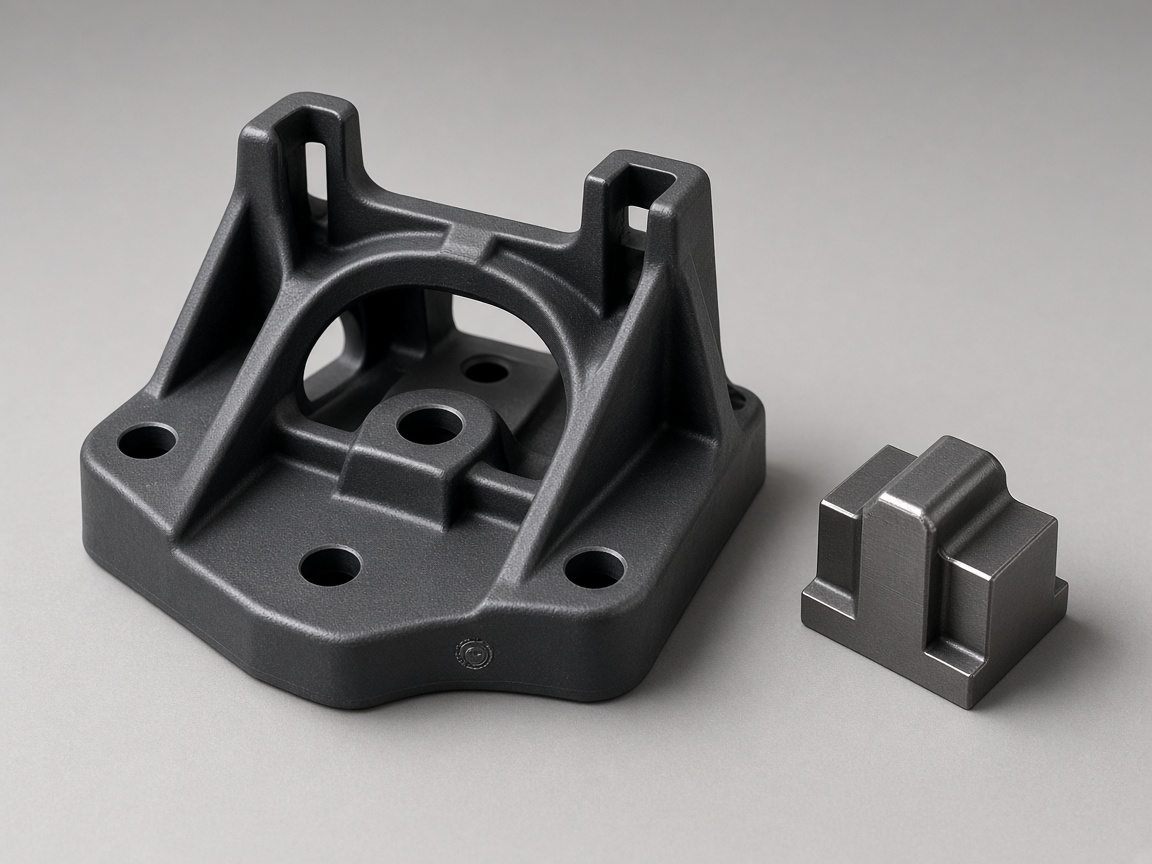
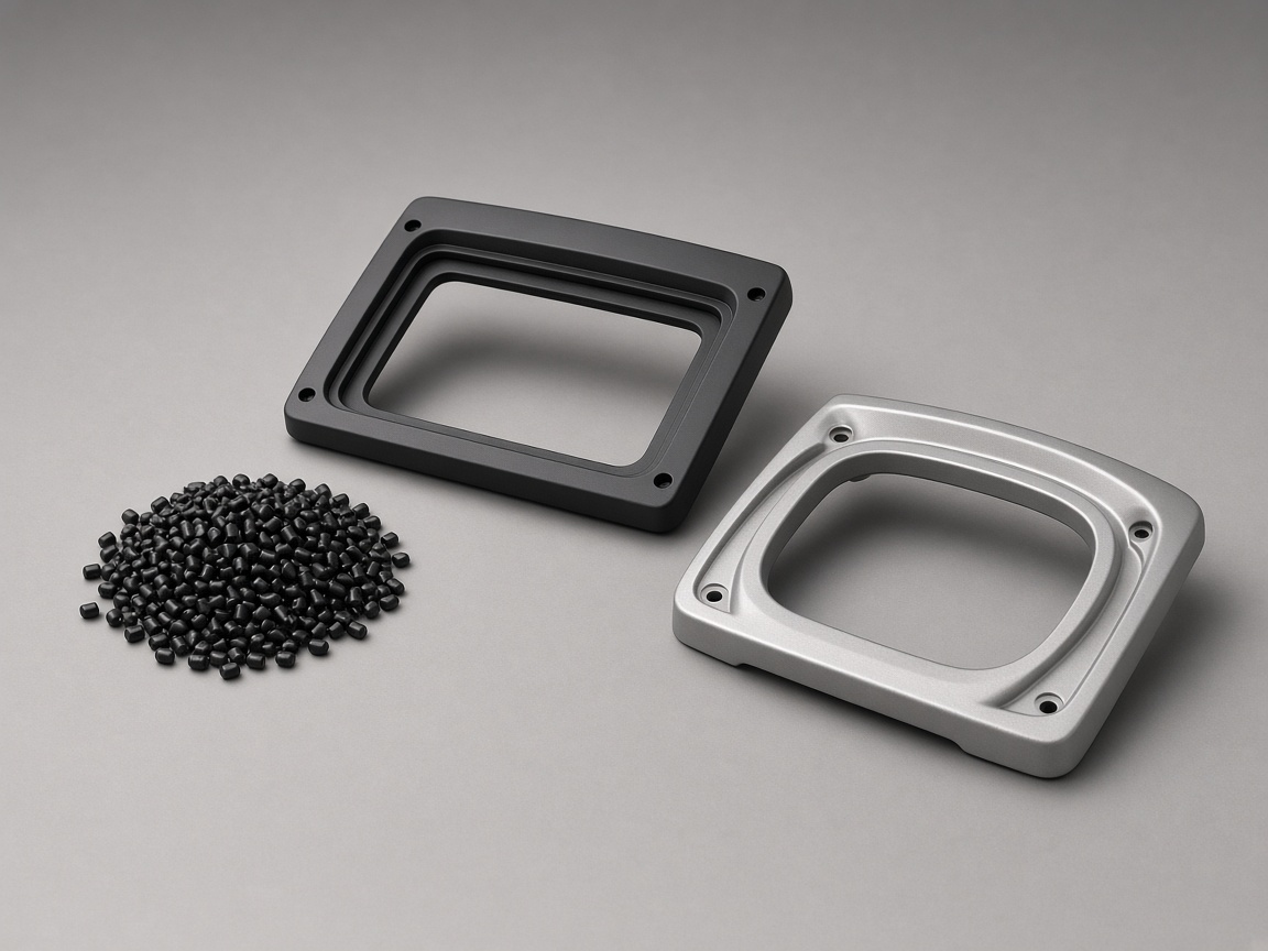
Plastic housing components from a steel tool
Plastic housing components from a steel tool
FAQ
The runner is the channel that delivers melt toward the cavity. The gate is the final restriction into the cavity. Runners can be cold or hot. Gates always define fill entry, shear, and vestige at the part.
Vestige is the small mark or remnant left where the gate separated from the part. Size and visibility depend on gate type, steel detail, and resin.
Match gate style to part geometry, cosmetic map, cavitation, automation, and resin sensitivity. Use the comparison table above, then confirm with mold design and mold flow review on large or cosmetic programs.
Yes. Location sets the pack path. A gate that freezes before thick sections receive pack can leave sink away from the gate. Asymmetric fill can also contribute to warp on long parts.
Minor adjustments to gate dimensions are sometimes possible in steel, but large changes may need insert rework or a new gate location. Specify cosmetic and fill constraints before final steel.
State constraints in project notes. Mold designers propose location on qualified tooling programs.
Not always, but weld lines on structural or cosmetic faces need explicit acceptance.
Small gates increase shear. Sensitive resins need gate sizing matched to process windows.
Next step
Upload CAD with cosmetic and assembly faces marked before approving steel.