Overmolding Plastic on Metal: RFQ Specs for Grips and Seals
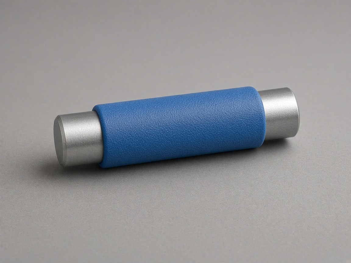
Overmolding plastic on metal means a metal insert or substrate is loaded into the mold cavity, and molten plastic is injected around or onto it so the finished assembly combines rigid metal performance with molded grip, seal, insulation, or cosmetic coverage. Teams searching for overmolding services usually already have a stamped, machined, or cast metal component and need the RFQ to spell out bond strategy, shutoff, and validation before tooling release. If you are still selecting the metal fabrication method, mention it on the RFQ so DFM can review compatibility with the overmold geometry.
NetProto builds a hardened steel injection mold for the program, provides DFM feedback on the uploaded CAD, and runs production on that same tool for repeat orders. If you are comparing an interim tool elsewhere, see soft tooling vs hardened steel for overmolding programs as a comparison, not as a NetProto tool menu. For the full process scope, see overmolding services.
What Does Overmolding Plastic on Metal Mean?
In injection overmolding services, the metal piece is not an afterthought added in final assembly. It is a process input: positioned in the cavity (or on a core pin), then encapsulated or partially wrapped by plastic in the same molding cycle. Common outcomes include soft-touch grips on steel handles, sealed zones around sensor inserts, insulated covers on bus bars, and structural brackets where plastic adds isolation or ergonomics without replacing the metal load path.
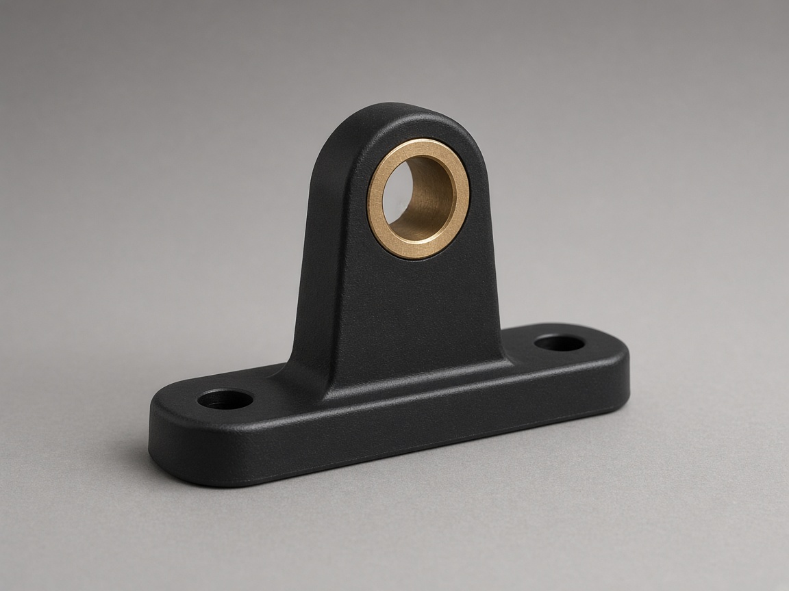
If the metal component is limited to a threaded bushing or a simple cylindrical insert whose main job is fastening, the program may align better with insert molding, where plastic forms around a discrete insert rather than a large substrate. The RFQ should still document insert source, tolerances, and retention requirements in either case.
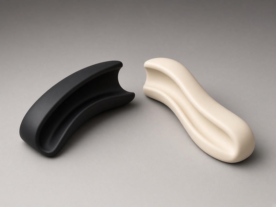
Soft-touch layers often use elastomeric or flexible thermoplastics. For skin family routing, see LSR vs TPE overmolding for soft-touch applications. Material selection for grips and seals is covered in Best Plastic for Overmolded Grips, Seals, and Soft Touch; this article stays on metal-side specification and mold shutoff.
Key Facts
- The metal substrate can be stamped, machined, sintered, or cast. It is not limited to threaded bushings alone.
- Bond strength or mechanical lock must be explicitly designed into the part. Do not assume plastic will adhere to bare metal without surface preparation or geometric retention features.
- Preheating, cleanliness level, and plating specification are process inputs that must be assigned as clear responsibilities on the RFQ.
- Shutoff along metal edges presents inherent flash and leakage risks that should be addressed during DFM review.
- Bond failure mechanisms have a dedicated article. Read our dedicated guide on overmolding bond failures for peel, delamination, and environmental attack instead of duplicating that analysis here.
- Epoxy potting or encapsulation is a chemically distinct process and should not be grouped with injection overmolding.
Related Process Guides
Use these pages when the design question is broader than metal RFQ fields:
- Insert molding versus large metal substrates and when to route simple cylindrical inserts there.
- Overmolding vs Two Shot Molding for tooling and bond tradeoffs at program level.
- Insert Molding vs Post Mold Assembly when debating in-mold integration versus later assembly steps.
- TPE Overmolding Adhesion checklist when the overmold layer is thermoplastic elastomer on a rigid substrate.
Metal Preparation and Mechanical Lock
Mechanical retention is the engineer's first line of defense when chemical adhesion is uncertain or when the assembly must survive pull, torque, or peel loads. Qualitative features that mold well include:
- Knurled zones where plastic can flow into surface texture
- Through-holes that let plastic form a rivet head on the far side
- Undercuts or dovetails that lock the overmold after cooling
- Edge grooves that trap a bead of plastic along a metal flange
Each feature adds tooling complexity and DFM scrutiny. Through-holes require core pins and venting; undercuts may need side actions or collapsible cores. Document which faces must remain bare metal for grounding, welding, or later assembly so the mold shutoff plan does not accidentally bury a critical surface.
Contamination on the metal surface is a common root cause of weak bonds. Drawing oils, stamping lubricants, laser oxide layers, passivation films, and plating bath residues can all block adhesion even when the plastic grade is marketed as "bondable." The RFQ should name the acceptable cleanliness standard in plain language (for example, "no visible oil," "plating vendor certificate required," or "customer supplies inserts in sealed bags after degrease") and assign who performs any preheat or surface treatment before the molding cycle.
For peel modes, environmental attack, and material pair pitfalls, see overmolding bond failures. This page stops at what to specify before tooling so those failures are less likely at T1.
Shutoff, Flash, and What T1 Must Prove
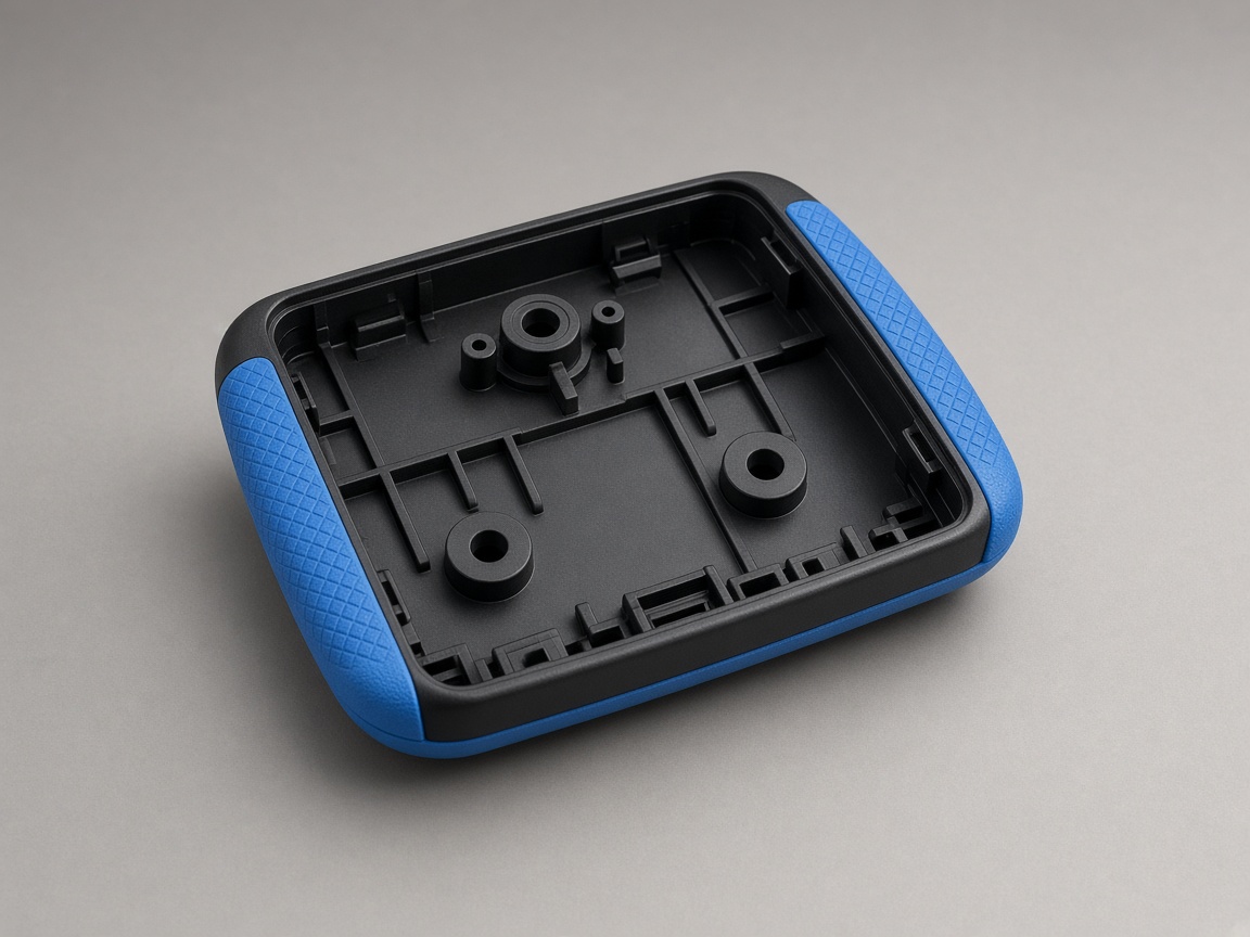
Shutoff defines where plastic flow must stop relative to exposed metal. Programs fall into three common patterns: full encapsulation (metal fully surrounded except where pins or terminals exit), partial wrap (grip or seal on one region while other faces stay metal for structure or heat sinking), and selective coverage zones (plastic only on defined pads for insulation or cosmetics). Each pattern drives a different shutoff line on the steel tool and different flash risk at the metal-to-plastic boundary.
Flash at a metal shutoff is not purely cosmetic. Thin flash webs can break off in service, compromise seal surfaces, or short electrical clearances. DFM should call out sharp metal edges that fight shutoff, coplanarity of the insert seat, and whether the insert is located by pins, rails, or cavity geometry. NetProto's mold team uses the uploaded assembly CAD to propose shutoff splits and venting before tooling release.
T1 sampling is the proof point for your functional intent. Define the sample size and acceptance criteria in your RFQ, not after T1 parts are produced. The RFQ must require the customer to state the leak, pull, or torque test in their own functional language. Examples include "no leakage at stated air decay pressure," "minimum axial pull-out force per your test fixture," or "no twist slip under specified torque." Those criteria belong to the product validation plan, not to a generic molding default. Pass/fail criteria for bond or pull tests belong on the customer drawing or RFQ; T1 parts are judged against that brief.
Cosmetic faces need the same explicit zoning as functional shutoffs. Mark which metal surfaces may show witness lines from shutoff contact versus which plastic surfaces are Class A. Separate cosmetic face (A-side) vs shutoff contact surfaces, and use SPI surface finish grades for overmold plastic per face rather than a single global callout. When regulated programs require documented validation scope, capture that on the RFQ and route detailed compliance questions through sales rather than assuming unlisted certifications.
RFQ Checklist
Use this checklist when preparing your plastic-on-metal overmolding quote package:
- Attach the metal part drawing or clearly note "customer-supplied insert" with dimensional callouts and material specification.
- State the plastic resin grade, or describe the grip, seal, or insulation target if the grade is still open (temperature, chemical exposure, flexibility, color).
- Mark shutoff edges and cosmetic face zones directly on the uploaded drawing or CAD model, including any keep-out zones for grounding or assembly access.
- Name the bond, pull, or leak test you will perform at T1 sampling, including the pass/fail criterion written in your validation language.
- Upload both metal and plastic bodies as separate solids or clearly identified volumes in the CAD assembly so DFM can review shutoff, venting, and mechanical lock features before the hardened steel tool is built.
Add notes on insert sourcing (molder-supplied versus customer-supplied), batch traceability if required, and any secondary operations such as pad printing or laser marking on the plastic zone after overmolding.